|
National MST Radar Facility |
||
|
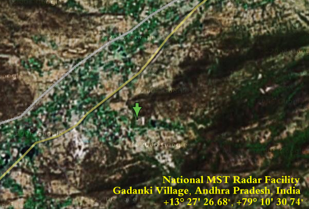
HAARP Like Facility +13° 27' 26.68", +79° 10' 30.74" ...
|
||
| ABOUT NATIONAL MST RADAR FACILITY
Indian scientists have carried out pioneering research work in the fields of astronomy and astrophysics, solar/interplanetary medium, earth's upper atmosphere/ionosphere, aeronomy/middle atmosphere and weather/climate phenomena. The nationally coordinated Indian Middle Atmosphere Programme (IMAP) was implemented during the period 1982-89 with well focussed campaign experiments with ground based, balloon, rocket and satellite based techniques. The IMAP programme led to the decision to conduct in-depth studies of atmosphericdynamical phenomena by developing a versatile ground based radar technique... ...The MST Radar is a state of the art instrument capable of providing estimates of atmospheric parameters with very high resolution on a continuous basis which are essential in the study of different dynamical processes in the atmosphere. It is an important research tool in the investigation of prevailing winds, waves ( including gravity waves) turbulence, and atmospheric stability & other mesoscale phenomena . A reliable three dimensional model of the atmosphere over the low latitudes improves our understanding of the climatic and weather variations... Establishment of NMRF Attaching great importance to the scientific utilisation
of the Indian MST Radar, the Government of India decided to create an autonomous
Scientific Society called the National MST Radar Facility (NMRF). This
society is affliated to the Department Of Space. The NMRF was registered
on January 11, 1993 under the Indian Societies Act 1860.
Location Of NMRF The scientific requirements dictated that the Indian MST Radar should be located preferably below 15 degrees North latitude. Hence after careful consideration of the various constraints, a site at Gadanki Village, near the temple town of Tirupati in the Chitoor district of Andhra Pradesh was selected for locating the Indian MST Radar . NMRF is located off the Chitoor -Tirupati main road in a picturesque landscape spreading over an area of about 42 acres. Regular train and bus services are operated between Tirupati and Bangalore/Madras. On request NMRF may provide transport between Tirupati and Gadanki. SOURCE:
The National MST Radar Facility (NMRF)
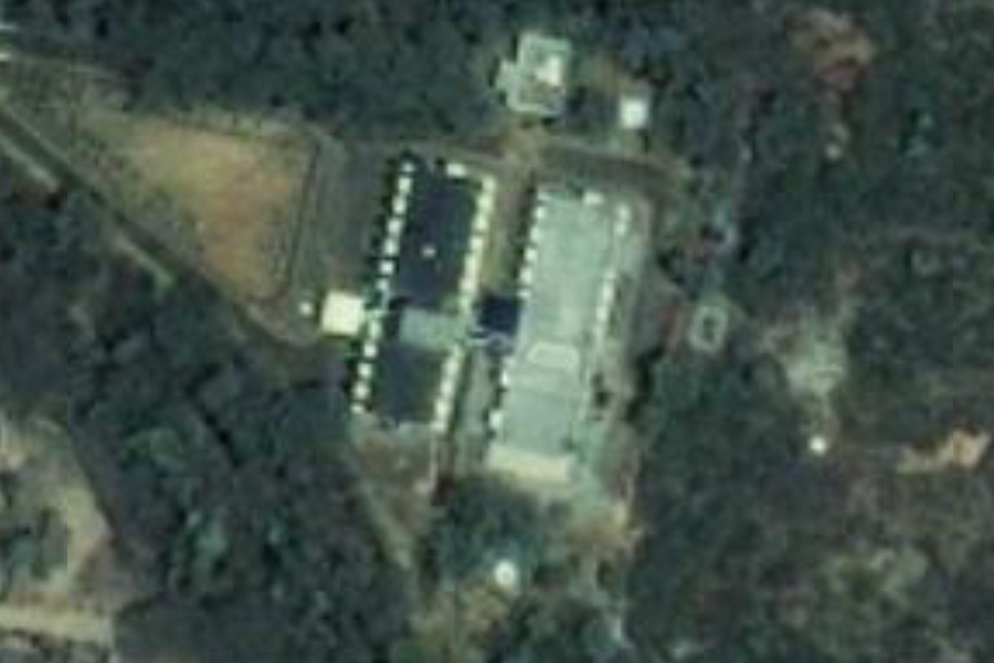
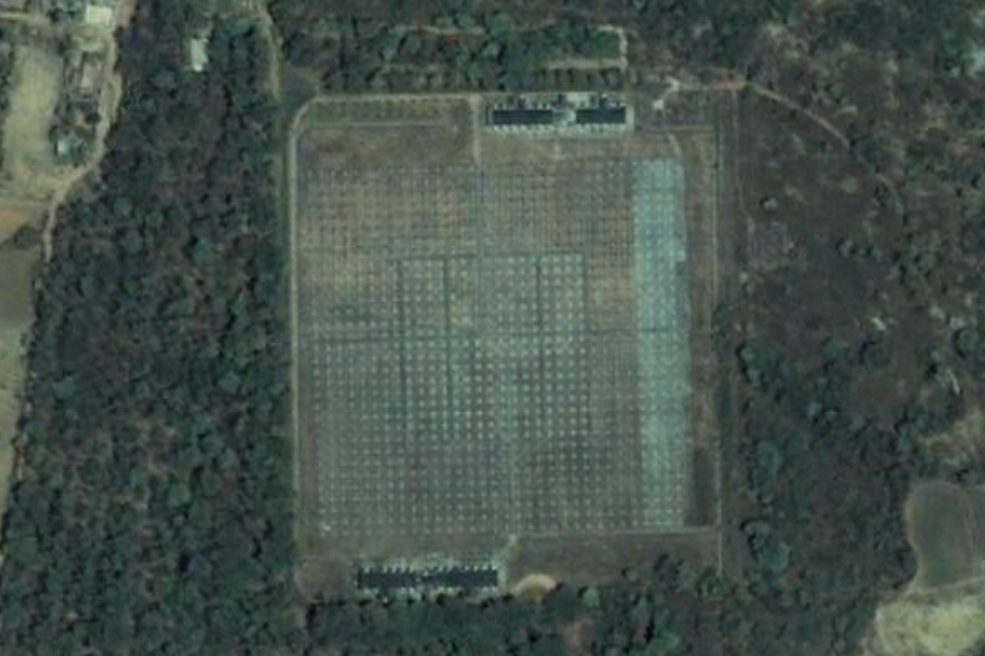
Like the HAARP Facility in Alaska, this is the best resolution available on Google Earth |
||
|
July 01, 2009 New Google Images National MST Radar Facility HAARP Like Facility +13° 27' 26.68", +79° 10' 30.74" ..
...
|
||
|
..
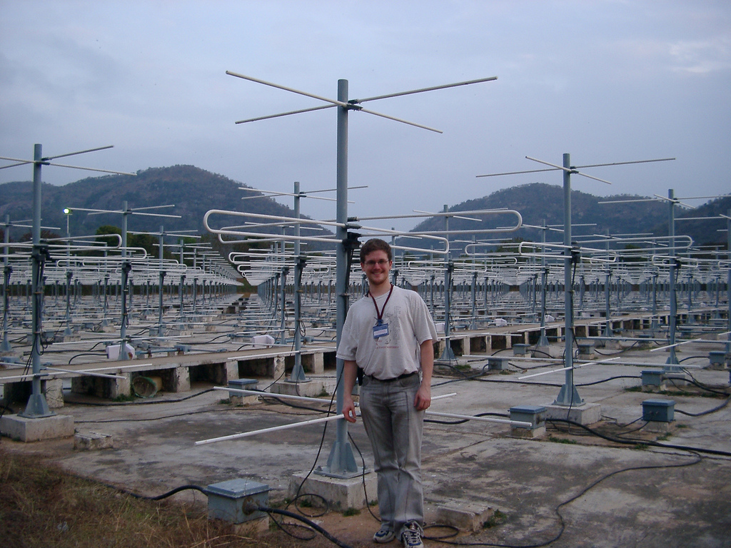
The Indian MST Radar is a highly sensitive VHF phased
array radar operating at 53 MHz with an peak power aperture product of
3 x 10¹⁰ Wm 2 .The system design specifications, including that of the
intermediate stage of ST mode , are presented below :
A total transmiting power of 2.5 MW ( peak ) is provided by 32 transmitters ranging in power from 20 kW to 120 kW, each feeding a subarray of 32 Yagis. To achieve the desired low side lobe level to the adiation pattern, the power is tapered across the array according to a modified Taylor distribution. The required power taper is accomplished in one principal direction by the differential powers of the transmitters and in the other direction by the series feed network . The transmitters can operate up to a duty cycle of 2.5%, limiting the total average power to about 60 kW. It is possible to transmit both coded and uncoded pulses with PRF in the range 62.5 Hz-8 kHz.The uncoded / coded pulses can be varied in pulse width from 1 to 64 microsec. A phase coherent reciever with quadrature channels
, having an overall gain of 110 dB , a dynamic range of 70 dB , and a bandwidth
matched to the baud length of the coded pulse, detects the weak back-scattered
signal. The switching of the antenna array between transmitter and receiver
is accomplised by T/R switches of hybrid coupler and PIN diode design.
A frequency synthesizer using a master oscillator with stability better
than one part in 1010 ( short term ) provides transmitter, carrier and
modulation as well as receiver injection signals, rendering the system
phase coherent . The quadrature outputs of the receiver are given to a
pre - processor unit consisting of two identical channels of A/D convertor
( ADC ), decoder and coherent integrator. The ADC is of 14-bit resolution
to match the dynamic range ( 70 dB ) of the receiver.The analog signal
in each channel is sampled and converted to digital at the rate of 1 MHz.
Specifications of Indian MST Radar |
||
| FAIR USE NOTICE: This page contains copyrighted material the use of which has not been specifically authorized by the copyright owner. Pegasus Research Consortium distributes this material without profit to those who have expressed a prior interest in receiving the included information for research and educational purposes. We believe this constitutes a fair use of any such copyrighted material as provided for in 17 U.S.C § 107. If you wish to use copyrighted material from this site for purposes of your own that go beyond fair use, you must obtain permission from the copyright owner. | ||
|
|
