|
SECTION IV (continued) DEVELOPMENT - TEST - PRODUCTION 4.2.7 COMMUNICATIONS 4.2.7.1 The manned lunar mission will require communications channels between the vehicles and earth and on the lunar surface for telemetry, T.V., voice, and vehicle control. Specific system parameters will depend on the characteristics of the ground tracking network and communications stations which will be used to support the lunar missions. 4.2.7.2 There are no significant technical problems associated with the development of equipment to perform the required communications operations. One exception to this general statement is that during re-entry radio transmission may not be possible at the lower frequencies utilised elsewhere in the mission because of the plasma shield set up by aerodynamic heating. One possible solution may be to provide a separate system operating at 10,000 mcs for re-entry. Overall savings in equipment weight, and power requirements will result from careful analysts and identification of requirements for information transfer and maximum utilisation of system components in a dual role. This will be done during the vehicle design phase. While not a requirement for early missions the capability to provide a secure communications link is desirable and will be considered during final design of the communications systems. A secure communications link will be a requirement in later missions. Throughout all phases, communications links critical to mission success should incorporate a high degree of protection against natural or man-made interference, or deliberate jamming. 4.2.7.3 The following Air Force projects will be reviewed and used to provide the necessary results required for the Lunex mission: 4335 (U) Applied Communications Research for Air Force Vehicles 4519 (U) Surface & Long Range Communications Techniques 5570 (U) Communications Security Applied Research 4.2.8 ENVIRONMENTAL DATA 4.2.8.1 Present knowledge of the lunar environment is extremely limited and it is necessary to obtain detailed information concerning the lunar composition, subsurface structure, surface characteristics, meteorite flux, level of solar and cosmic radiation, and magnetic field. This knowledge is required to design the equipment for the Lunex program so that personnel may be protected and the mission accomplished. 4.2.8.2 The importance of lunar composition in manned exploration of the moon lies largely in the ability of the moon to provide fuel for vehicles and secondary power, as well as to supplement life support systems with additional water, radiation shielding material, and semi-permanent shelters. Of these lunar resources, water appears to be of major importance both as a fuel and in life support. Water will probably be present both as ice in permanently shadowed zones and as water of hydration in certain minerals such as serpentine. 4.2.8.3 Present knowledge of lunar composition is almost entirely theoretical. The relatively low lunar density (3.34) indicates low metal content. By analogy with the compositions of meteorites it is generally assumed that the moon is composed of chondritic (stony meteorite) material. That this assumption is only partially valid is demonstrated by the fact that chondritic meteorites would have to lose about 10% of their iron content in order to attain this lunar density. 4.2.8.4 The Air Force and NASA are presently trying to determine the lunar composition indirectly through study of tektites, which may be fragments of the moon, and through study of micrometeoritic dust captured above the atmosphere. (Air Force efforts are funded under Project 7698). 4.2.8.5 The Air Force is trying to determine the lunar composition directly by means of spectrometric analysis of the natural X-ray fluorescence of the moon due to the bombardment of the lunar surface by solar radiation. The first knowledge of lunar composition is anticipated in March of 1962. (This work is also funded under Project 7698). 4.2.8.6 NASA intends to measure the lunar composition directly by means of its Surveyor lunar probe now scheduled for mid-1963. 4.2.8.7 Neither Air Force measurements of overall lunar composition, nor NASA measurements of spot compositions will satisfy the requirement for location of lunar resources. The NASA Prospector vehicle scheduled for 1966 will obtain more widespread data, but that is urgently needed is detailed knowledge of the variation of lunar composition over the whole surface. This can only be accomplished by a lunar orbiting vehicle with appropriate instrumentation. NASA presently has this planned for 1965 and the appropriateness of their instrumentation remains in doubt. Also this is too late to meet the requirements of the Lunex program. 4.2.8.8 The importance of lunar subsurface structure in exploration of the moon lies largely in a possible collapse hazard under vehicles and personnel, and in the possibility of utilising subsurface structures as shelters and storage facilities. Present knowledge of lunar subsurface structure is based on a theoretical extrapolation from the presumed origin of the surface features. The majority of lunar geologists believe that lunar craters were formed by means of the impact of large meteorites, and that only limited volcanism has occurred in the lunar highlands. The maria, on the other hand, are thought to be giant lava pools; although the melting is assumed to have been triggered by asteroidal impact. Based on these theories of origin for the lunar surface features, it is thought that the subsurface structure of the lunar highlands will consist largely of overlapping layers of debris ejected from the impact craters. The collapse hazard of such material is negligible. The maria should be covered by no more than 40 feet of vesicular (bubble filled) lava, with maximum vesicle (bubble) size about six feet in diameter. Such terrain could present a collapse hazard, the severity of which will depend upon actual (rather than maximum) vesicle size. It should be noted, however, that a rival theory for the origin of lunar craters holds that they were produced by volcanism as calderea. Should this theory be correct, the collapse hazard in the highlands would probably exceed that on the maria. In order to determine the lunar subsurface structure, it is necessary to place instruments on the moon. Thus, the Air Force, although contributing theoretical evaluations an described above (under Project 7698), has no program for directly determining lunar subsurface structure. NASA plans to place seismometers and a coring instrument in the Surveyor vehicle in mid-1963 to determine these parameters. Again, point measurements are not sufficient, and geophysical instrumentation adequate for determining subsurface structure from the lunar orbiting vehicle (1965) should be developed. 4.2.8.9 The importance of lunar surface characteristics lies in their critical importance in design of both rocket end surface vehicles and in lunar navigation. Critical surface characteristics include gross topography, microtopography, and the nature of the lunar dust. Of these characteristics, knowledge of gross topography will be important in overall rocket design and in design and operation of rocket landing and navigational equipment. The microtopography (relief less than 20 feet) will be important in the design of rocket landing equipment and the vehicle for surface exploration. The nature of the surface dust will be moat important in design of the vehicle for surface exploration. Present knowledge of gross topography shows that slopes are generally gentle, and topographic profiles have been determined over a limited amount of terrain. Present knowledge of microtopography is very limited. Radar returns, once thought reliable indicators of low microrelief, are now considered by moat space scientists to be so poorly understood that conclusions may not be drawn from them. Photometric data appears to indicate a rather rough surface, but this data is also subject to more than one interpretation. Present knowledge of the nature of the lunar dust is entirely theoretical. The leading school of thought holds that the dust is compacted and sintered. An opposing school holds that the dust bears an electrostatic charge. Should the dust bear an electrostatic charge, it would be very loose and probably subject to migration. The hazard to surface vehicles and even personnel is apparent. Gross lunar topography on the visible face is presently being mapped by the Aeronautical Chart and Information Center based on techniques developed under Project 8602. Maximum resolution is about 1/3 mile, and average resolution is about one mile. Higher resolution photography and photography of the back side of the moon will be obtained by the lunar orbiting vehicle planned by NASA for 1965. A co-operative effort by ACIC and NASA is presently envisioned to produce the necessary topographic lunar charts. Microtopography is being studied by the Army Corps of Engineers through radar experiments. (the Air Force work is being done on the Millstone radar equipment) The nature of the lunar dust is being studied primarily by the Air Force under Projects 7698 and 8602 by means of radiometrlc studies from high altitude unmanned balloons and results are anticipated in early 1962. NASA anticipates obtaining at least partial data on the nature of the dust from Surveyor (mid-1963) by television observation of the lunar surface and by the landing characteristics of the vehicle. 4.2.8.10 The meteorite flux and level of solar and cosmic radiation near the lunar surface are important for the survival of personnel either on the lunar surface or in vehicles and shelters. Present knowledge of these parameters is fairly precise as a result of satellite and deep space probe experiments by NASA and the Air Force. Only the radiation environment within the first few meters of the lunar surface is still speculative as a result of uncertainties in our knowledge of the interaction of solar and cosmic radiation with the lunar surface materials. It seems likely that a cloud of ions will be produced by radiation bombardment as well as secondary X-rays. The density of the electron cloud is unknown, and may be critical for lunar communications. The Air Force is studying the lunar and cislunar radiation environment under Projects 6687, 6688, 7601, 7649, and 7663 by means of satellites, deep space probes, and vertical sounding rockets. The NASA Surveyor vehicle (mid-1963) should give detailed knowledge of the radiation environment at the lunar surface. 4.2.8.11 The lunar magnetic field may be important to space and lunar surface navigation, and in its effects on ionised lunar materials. The Russian Lunik II indicated that the lunar magnetic field must be very small. The Russians were not clear on how small, but it is generally thought that the moon does not possess a magnetic field. Thus, all magnetic effects should be derived from the very low intensity interplanetary field and magnetic fields, "frozen" into solar plasmas. The Air Force is studying the interplanetary magnetic field under Project 7601. NASA should be able to determine the field near the lunar surface by means of the Ranger vehicle during 1962, and the field at the surface by means of Surveyor (mid-1963). 4.2.8.12 Two facts are apparent from a study of the data outlined above. First, one Air Force project (7698), which was funded for only 250K in 1962 and 300K in 1963, is responsible for moat of the research on the lunar environment. More funds are required for a speed-up in this program. Second, many critical experiments are tied to the NASA lunar orbiting vehicle, which has not been considered a very important vehicle by NASA. This program is essential to the Lunex and should be speeded up and planned more carefully. 4.2.8.13 Effort on Air Force Project 7698 will be increased substantially to insure that data necessary for the Lunex mission is available. A close working relationship will be established with NASA to provide, if possible, the inclusion of Air Force requirements in their planning for lunar programs both as regards to objectives and scheduling. 4.2.9 MATERIALS 4.2.9.1 The lunar expedition imposes rigid requirements on materials to maintain their characteristics while subject to radiation, vacuum, temperature extremes, and meteorites. This problem must be considered by the individual subsystem design. It is intended to point out here the overall material problem and programs which will contribute to its solution. 4.2.9.2 The absence of an atmosphere on the moon increases the radiative flux (particle and electromagnetic) from the sun and as such potentially increases the possibility of damage to man and lightweight plastic structures through the formation of free radicals and subsequent depolymerisation. The need for lightweight shielding is apparent. The vacuum conditions of the moon would aggravate the problems associated with moderately volatile constituents of plastics, lubricants, etc. For instance, the relatively volatile plasticizers in a plastic material could evaporate and interfere with the plastic function. Finally, the results of impact of micrometeorites on structural materials must be determined. All desirable properties must be acquired without penalty of weight. In addition to the problems encountered on the Moon, similar problems are encountered while in transit. In particular the heating encountered on re-entry into the Earth 'e atmosphere at 37,000 feet per second presents a severe material problem. 4.2.9.3 Some of the specific material requirements that can be identified are: a Lubricants that will function for long periods of time in a vacuum and temperature conditions such as exist in the moon. b. Materials that will not sublimate in a vacuum at moon temperature. c. Light-weight shielding material against meteorites. d. Light-weight radiation shielding. e. Shock-absorbing material that will function at 330 degrees F. f. Coatings that will resist radiation, especially during periods of solar flares. g. Glues and adhesives that will function with lunar materials. 4.2.9.4 Present projects to raise the level of technology in materials are listed below. They will be supported as required to insure success of the lunar mission. 7312 (U) Finishes and Materials Preservation. 7320 (U) Air Force Textile Materials. 7340 (U) Non-Metallic & Composite Materials. 7351 (U) Metallic Materials. 7371 (U) Applied Research in Electrical, Electronic, and Magnetic Material. 7391 (U) Energy Transmission Fluids. 4.2.9.5 While work in the basic research program cannot be counted on to provide technical breakthroughs within the time schedule of the Lunex program, materials study of this type will be monitored so that all technical advances can be integrated into the Lunex program. Specific examples of projects of this type are: 8806 (U) Research on Materials at High Temperature. 7022 (U) Surface and Interface Phenomena of Matter. 9760 (U) Research in Properties of Matter. 4.3 TEST PLAN The development and production of the equipment for the Lunar Expedition will require a concurrent and detailed test program. The test program will be carried out on the basis of research tests to establish design criteria, materials tests, component tests, and finally, a progressive series of tests as components are assembled into subsystems and major systems and structures. Integration tests for flight suitability will be conducted for all functioning systems and the complete vehicle. Payload effects on the booster structure will be determined with a simulated payload. Subsequently, a flight-type payload will be used to demonstrate booster-payload system compatibility, reliability, crew safety, and mission performance. Emphasis will be placed early in the program on research tests to derive basic design criteria, define the configuration and determine aerodynamic parameters. Tests are to be run at progressively higher levels as the design evolves. Thus, entire subsystems, combined subsystems and complex major structures are to be subjected to evaluation tests as necessary to investigate component and subsystem interactions, or to prove out complex structural designs. A captive test vehicle firing program will be the culmination of ground development testing. The over-all objective of the captive-firing program is to demonstrate satisfactory integration of the propulsion system with other vehicle systems that have an interface, direct or indirect, with the propulsion system. The early tests will be conducted in a simulated vehicle with the airborne vehicle systems installed on a heavy-wall propellant tank section. The tanks will be supported by a test stand structure which will also restrain the tanks against propulsion system thrust forces. For final testing a flight-type configuration will be used during captive tests. Flight testing of the High-Speed Re-entry Test Vehicle, the Abort System, and Orbital, Circumlunar and unmanned lunar landing and Return Vehicles will complete the development program. 4.3.1 TEST CATEGORIES 4.3.1.1 RESEARCH TESTS Tests will be run in appropriate research laboratories to define basic design criteria in at least the following technical areas: a. Propulsion b. Heat transfer c. Aerodynamic forces and pressures d. Materials e. Statics (structures) 4.3.1.1.1 Propulsion Tests -- Wind and vacuum tunnel testing will be conducted to investigate the problems of multiple re-start in a vacuum environment, to develop throttleable techniques, to determine lunar landing problems, and to determine the desirability of using the same engines for lunar landing and lunar launching. Tests will be made to evaluate the propulsion stage for the circumlunar flights and to determine the capability of the abort propulsion system to accomplish its objective. 4.3.1.1.2 Heat Transfer Tests -- Testing will be required on the insulation for the liquid hydrogen tanks to determine: a. Optimum material thickness and weight b. The amount of liquid hydrogen boil-off c. the air leakage through seals d. The airload effect on structural integrity The thermal bowing of insulation panels f. The separation distance between panel and tank skin Scale-model or modified full-scale air-conditioning tests will be conducted on engine components, adapter sections and flight equipment storage areas. Heat transfer characteristics for selected materials, structures, and surfaces will be required to support the engineering design. 4.3.1.1.3 Aerodynamic Force and Pressure Wind-Tunnel Tests -- Wind-tunnel model tests of the launch vehicle and payload configuration will be required to accurately determine the aerodynamic forces and moments imposed on the vehicle during the boost trajectory. These tests will provide data for determination of structural design criteria, aerodynamic stability and control parameters, and the performance penalty incurred by aerodynamic drag. The test program will include both force and pressure measurements through the flight Mach number range for which these effects are significant. Wind tunnel testing of selected shapes at velocities never before studied will be necessary to determine re-entry vehicle characteristics. Particular emphasis will be placed on control surface capability and heating problems. Manoeuvrability limits, g loadings, re-entry corridor characteristics and subsonic landing characteristics must be determined in support of the engineering design program. Integration and correlation of the ground wind-tunnel testing with the high-speed re-entry flight test program is essential. 4.3.1.1.4 Material Tests -- A materials development test program will be undertaken to determine the allowable design strength values and provide design information on the selected structural materials over the appropriate temperature ranges for the base metallic, ablative surfaces, and welded joints. Particular emphasis will be placed on tendency toward brittle fracture under service conditions and in selecting materials for re-entry at 37,000 ft/sec. The testing program will consist of at least the following: Materials. a. Smooth and notched static tensile tests of the selected materials. b. Static tensile tests of welded joints, both fusion- and resistance-welded, for the selected joint configuration for each type of sheet material. c. Smooth and notched static tensile tests of the selected extrusion and forging materials. d. Notched impact tests of the extrusion and forging materials. e. Low-cycle, high stress fatigue tests of welded joints made by the fusion and resistance methods for the selected joint configurations in sheet materials. This data will be accumulated for the appropriate temperature ranges, i.e., from elevated re-entry temperatures to the cryogenic temperatures in the tanks, as dictated by the projected environmental requirements. In addition, supporting tests such as metallographic examinations and chemical composition determinations will be made as required. 4.3.1.1.5 Static Tests -- static test program will include design load structural substantiation testing to demonstrate structural integrity of the Manned Lunar and Cargo Payloads. Structural substantiation testing to design loads and temperatures will be accomplished on a full-size stub tank, identical (except for length) to the Lunar Landing Stage tank. This will ensure that load introduction and takeout will be representative of the flight article. One complete interstage adapter will be tested to ultimate design loads under appropriate environmental conditions. The adapter will be attached to a stub tank identical to the Lunar Launching Stage tank section in every respect except length, to ensure realistic load introduction and takeout. A stub tank will also be used to demonstrate the integrity of the Lunar Launch Stage tank construction under design loads and environments. Methods of introducing the payload vehicle loads into the adapter section and thus the Lunar Launch Stage tanks will be determined. Tests will also be run on full-size tank bulkheads. These will be attached to a segment of typical tank structure, adequate to allow the bulkhead behaviour to be representative of that of the flight article under design conditions. These bulkheads will be tested to ultimate design loads to ensure their structural reliability at all points within the flight regime. Ground handling equipment tests will cover critical fittings and joints for structural substantiation of these items under design conditions. 4.3.2 DESIGN EVALUATION TESTS Component design evaluation testing is defined here as informal testing conducted by the vehicle contractor, or vendor test labs, for the purpose of basic design evaluation prior to production release, sad to pinpoint critical areas in prototype packages. Qualification testing is defined as those formal tests performed on flight-type hardware to demonstrate compliance with design specifications. A qualification test plan will be prepared approximately 90 days after engineering go-ahead outlining the qualification test conditions. The qualification tests are to be performed in strict accordance with written and approved detailed test procedures, and witnessed by the Air Force, or an approved representative. The vehicle contractors' test laboratories will conduct these tests, or subcontract and supervise them at an independent testing agency. Components to be tested will be determined during the engineering design effort. Controlled environmental conditions will simulate conditions that airborne and ground support equipment are expected to experience during manufacturing, shipping, storage, pre-flight and flight. Environmental testing conditions will be established based on data already obtained in research and development programs on large rocket-powered vehicles and associated support equipment. Conditions for shipping, storage and handling environmental tests are established in current military and commercial specifications. Subsystem, combined subsystems, and structural evaluation tests will be run in appropriate laboratory faculties to investigate component and subsystem interactions, and to prove out structural designs. Acceptance test procedures will also be developed for use in the factory on deliverable hardware.
A test plan describing the basic conditions and test objectives of each factory systems test, along with the checkout parameters and recorded evaluation data, will be prepared. A final acceptance test will be required at the time the contractor delivers the vehicle to the Air Force. Test conditions will be as close to the flight conditions as is feasible and safe. All systems will be energised and operated simultaneously. A final acceptance test evaluation document will be prepared for use by the Air Force and the contractor in determining compliance with test requirements. Systems acceptance test procedures will be based on all critical parameters required to determine proper functioning of each system in accordance with design specifications and drawings. This will assure a co-ordinated effort of vehicle design, test equipment design, and factory acceptance testing. 4.3.3 FLIGHT TESTING The Lunex flight test program represents a long and expensive effort leading to the first manned landing on the moon. It requires basic research flights, equipment checkout flights, capability demonstration-flights and finally, the manned and cargo Lunar Expedition flights. This type of effort can only be achieved efficiently and at a minimum cost if the end objective is always clear and the program is designed to meet this objective. The Lunar Expedition flight test program will provide many side, but important apace capabilities. For example: in April 1965 the first orbital flight capability in a true apace vehicle will be possible; in September 1966, man will make his first flight around the moon in a fully manoeuvrable and recoverable re-entry vehicle; and in August 1967 the first men will land on the moon. Essentially these can all be called test flights, but in each case the system is only at the beginning of its capability instead of being a dead-end item. Each of these capabilities may readily be expanded to provide a military capability if necessary. The flight test program is summarised on the Lunar Expedition Test Schedule. The following major objectives will be accomplished in the indicated part of the test program. 4.3.3.1 HIGH-SPEED RE-ENTRY FLIGHT TEST Since present wind-tunnel capabilities are limited to approximately 18,000 ft/sec., it is necessary to perform re-entry flight testing at velocities that range from 25,000 to 45,000 ft/sec. The major objectives of this test program are to:
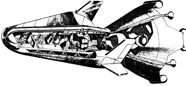
a. Verify or disprove present theories on basic re-entry techniques as extrapolated to the stated velocity range. b. Determine problem areas and develop new fundamental theory, numerical procedures and testing techniques where required for this re-entry range. c. Identify the following: (1) Items that can be investigated further on a laboratory scale. (2) Specific laboratory facility requirements. (3) Additional flight tests that must be performed. d. Support the engineering design program for the Lunex by providing the above data and special shape testing if required. 4.3.3.2 Lunex RE-ENTRY VEHICLE FLIGHT TEST The Lunex Re-entry Vehicle will be flight tested by various techniques and in varying environments. Each test will be designed to allow the vehicle to proceed to the next more difficult step. The major testing steps are presented below, with the major test objectives for each step. a. Prototype Drop Test Prototype vehicles will be drop tested from a B-52, or equivalent, in both an unmanned and a manned series of tests. Each series will be designed to: (1) Establish landing characteristics. (2) Measure inherent subsonic, transonic, and hypersonic stability and control characteristics of the vehicle. (3) Explore the flight characteristics of the re-entry vehicle in every possible portion of the Mach number spectrum. (4) Train Lunex crews. b. Orbital Test: Maximum use will be made of SAINT orbital test information and unmanned and manned flights will be accomplished. These tests will demonstrate: (1) The capability of the Lunex Re-entry Vehicle to operate in the orbital area. (2) Re-entry capability at velocities of 25,000 ft/sec. (3) The manoeuvrability of the re-entry vehicle and its capability to land at a pre-selected earth base. c. Circumlunar Test This flight will use the Circumlunar Propulsion Stage and the Lunex Re-entry Vehicle. The major test objectives are: (1) To send an unmanned and then a manned vehicle around the moon and return to an earth lending at a selected base. (2) To check out guidance, flight control, guidance, communications and life support sub-systems in a true space environment prior to landing on the lunar surface.
(3) To perform manned reconnaissance of the lunar surface. d. Lunar Landing and Return The unmanned vehicle flights will check out the Manned Re-entry Vehicle and related systems to provide a completely automatic system before man first tries the most difficult step in the Lunex program. The major test objectives for these flights will be to: (1) Check out the Lunar Landing and Lunar Launching Stages. (2) Check out the Cargo Payload's ability to deliver cargo packages to a preselected site on the lunar surface. (3) Place three men on the lunar surface so that the initial surface reconnaissance can be accomplished prior to the arrival of the Lunar Expedition. 4.3.3.3 LUNAR LAUNCH STAGE FLIGHT TEST The Lunar launch Stage will be initially checked under orbital conditions to: a. Demonstrate space environment operation. b. Demonstrate engine restart after "soaking" in apace for an extended period. c. Demonstrate automatic checkout, communications, and remote control capability. The Lunar Launch Stage will then be flight tested with the complete Manned Lunar Payload for the unmanned and manned Lunar Landing and Return Missions. 4.3.3.4 LUNAR LANDING STAGE FLIGHT TEST The Lunar Landing Stage will be initially checked out by drop testing. These tests will: a. Demonstrate landing techniques and the capability of the selected landing system. b. Evaluate the effects of unexpected terrain variation. c. Determine the effects of malfunctioning equipment during the landing manoeuvre. d. Evaluate the effects of engine blast on landing surfaces similar to the predicted lunar surface. The Lunar Landing Stage will receive its first space evaluation in orbit. The major objectives are: a. Correlate drop-test data with orbital or space operations. b. To determine the effects of space environment on the stage. The first Lunar Landing with the Lunar Landing Stage will be accomplished with a Cargo Package as the payload. When this has been completed a Lunex Re-entry Vehicle will be landed unmanned. The test objectives are to: a. Demonstrate the feasibility of landing large cargo packages on the lunar surface. b. Demonstrate the feasibility of automatically landing a "manned vehicle" while unmanned. c. Provide a man-rated system for the Lunar Expedition. 4.3.3.5 CARGO PACKAGE CONFIGURATION Various configurations for the Cargo Package of the Lunex Cargo Payload will be tested. The objectives are to: a. Determine the Cargo Payload aerodynamic characteristics. b. Demonstrate that the Cargo Packages can be delivered where desired on the lunar surface. 4.3.3.6 ABORT SYSTEM FLIGHT TEST The fact that a system of this magnitude must possess some measure of "unreliability" is recognised and a "fail safe" abort system is required to insure the survivability of the crew. The test objectives for the Abort System Flight Test Program are to: a. Demonstrate that crew members in the manned Lunex Re-entry Vehicle can be recovered safely in the event of a malfunction. b. Demonstrate that the Space launch System is capable of shut-down, or thrust vector change, so that crew abort is possible. 4.3.4 CHECKOUT AND TEST EQUIPMENT The test equipment will be fully automatic with quantitative readout capability for all critical functions. The Lunex checkout equipment will be the same, or compatible with the Space Launching System checkout equipment. The equipment will be capable of checking out the complete booster and payload system as well as any individual, or isolated component, or subsystem. It shall be fully capable of checkout of any one stage, or the re-entry vehicle, as an isolated unit, and will mate with the stage interface functions and furnish appropriate operational or simulated error inputs to the stage systems. For the time period of interest, it ii entirely practical to incorporate malfunction prediction capability for preventative maintenance. This will entail a computer function which will accurately control and record the input and output signal values to each system or component. Variations in operation will be recorded and compared to predetermined failure values or characteristics and will forecast the remaining service life of the system under test. The checkout equipment shall be installed in each blockhouse and it may be used in conjunction with the launch area. This same equipment shall be utilised in the vehicle manufacturing checkout and test functions, as well as in the launch complex, receiving inspection, and maintenance facilities. The blockhouse equipment will monitor the launch control system commands and inputs as well as those of the payload. Because the launch control equipment will display only go/no-go signals, the checkout and test system will furnish quantitative displays of any function under question for human appraisal and decision. When the systems are flown unmanned and on the early manned lunar flights it will be necessary to provide automatic checkout where appropriate via a telemetry link. As an example, prior and during lunar launch the checkout procedures will be monitored at the earth control station via the telemetry link. 4.4 PRODUCTION PLAN At the present time a detailed Production Plan is not available. However, the present preliminary design study will be completed on 30 June 1961 and the final report to be provided by six independent contractors will include their proposed Production Plan. When the study results have been evaluated a Production Plan for the Lunar Expedition will be prepared . Several points are apparent at this time and they are presented for completeness in this plan. 4.4.1 QUANTITY Limited quantities of early equipment will be required until the test program improves and increases the capabilities of each item and production quantities became possible. Then, as development and testing proceeds the equipment will become more standardised and production techniques will become more applicable. When the Lunar Landing and Return flights are initiated it will be necessary to launch vehicles at rates that vary from one to two flights per month. When the Lunar Expedition is actually underway the launch rate will remain at a rate of two per month for an extended period. Considering the size, weight, complexity, and importance of these vehicles this represents production rates even when compared to past aircraft or missile production programs. 4.4.2 QUALITY The inherent reliability of the systems required for the Lunar Expedition program will be maximised by good design practice. Reliability testing represents a major effort of the test program, but the achieved reliability of these systems can only be maintained during production by an excellent quality control program. This means that good organisation, adequate manning and early recognition of the quality control problem is essential. Close co-ordination is required between the quality control personnel and the reliability personnel in the design, development, and test program if the reliability program and the test results are to provide the proper guidance so that quality can be maintained throughout the production effort. 4.4.3 LOCATION It is anticipated that most of the major systems and sub-systems can be manufactured at facilities, or locations presently in existence and available to the aerospace industry. However, the possibility does exist that certain items, such as the first stage solid propellant stage, may be manufactured at the Lunar Launch Complex due to its size and transportation limitations. These particular items have not been specified at this time, but this will be done as soon as possible. SECTION V. BUDGET AND FINANCIAL 5.0 INTRODUCTION The funding estimates for the Lunar Expedition Program are based on results obtained from previous concept, feasibility, and preliminary design studies. These results were published in Lunar Observatory Final Report, Volume I - Study Summary and Program Plan, numbered AFBMD TR 60-44 and dated April 1960. The costing of this program was accomplished by the Rand Corporation and was based on a completely integrated program. The funding estimates for the Lunar Expedition represent all the costs of establishing a habitable facility on the moon except the cost of developing the Space Launching System. This funding would include a Lunar Transport Vehicle development program that would give the US the capability of using the moon and space. Then if the need should develop in the future, the Lunar Expedition Facility could be expanded to support military operations. Studies have shown that the moon possesses real military potential and it could support a recallable deterrent capability. The development of the Lunar Transport Vehicle represents a minimum program for the Air Force to obtain control of the cislunar volume and the lunar surface. 5.1 BUDGET ESTIMATE AND FINANCIAL PLAN A preliminary design for the Lunar Transport Vehicle is presently being accomplished by six contractors on an active study program. This program was funded for $300,000 in FY 61 and three of the contractors are each performing the design under a $100,000 contract. The other three contractors are participating on a voluntary basis. The final reports for this preliminary design will be submitted to the SSD on 30 June 1961. Evaluation of these reports will follow immediately and the results will be used to revise this document where necessary The Lunex program has an Engineering Design competition scheduled for initiation in January 1962. This competitive effort would be evaluated and a decision on the manufacturing approach would be possible by January 1963. To accomplish this program the following funds will be required: FY 62: $ 26.9 million FY-63: $ 112.2 million Should the above funds not be made available, the schedule for establishing the Lunar Expedition will be delayed proportionally to the delay in funding. Launch Facilities Expedition Costs 5.2 COST ESTIMATES The funding requirement for the complete Lunex Program are as follows: FY COSTS (in millions of dollars)
To accomplish the Lunex Program, addition information about the lunar surface is required at an early date. This means lunar surface photographs from a lunar orbiting vehicle and the delivery of a radio-light beacon to the lunar surface by a soft landing vehicle. Present NASA programs will provide some information and capability. However, to meet the Lunex program schedule, the following additional funding will be required by either the NASA or the Air Force: Unmanned Vehicles - FY COSTS (in millions of dollars)
5.3 FY 62, 63 FINANCIAL PLAN
Continued at Lunex -
Chapter 4
Last update 12 March 2001. Contact Mark Wade with any corrections or comments. Conditions for use of drawings, pictures, or other materials from this site.. © Mark Wade, 2001 astronautix.com |